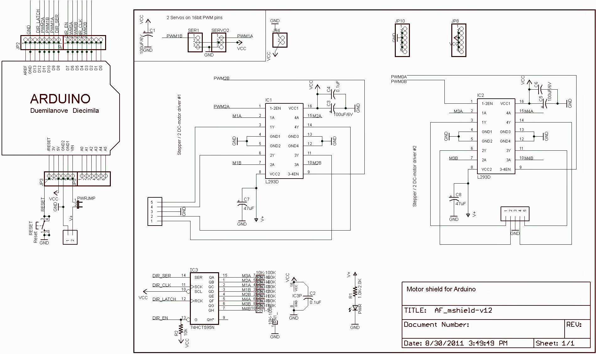
L293d Motor Driver Circuit Diagram Pdf
Aug 16, 2013 - L293D Motor Driver IC is a simple 16 pin dual H-bridge IC for DC motor. Find Pin diagram, Circuit diagram working and description with voltage. Dc motor controller diagram image wiring library. Location based locking system for transportation. Pdf microcontroller based smart home monitoring and control system. Dc motor controller diagram image wiring library. Dc motor controller diagram image wiring library. Pcb layout of ultrasonic radar micro controller projects.
The L293 and L293D are quadruple high-current half-H drivers. The L293 is designed to provide bidirectional drive currents of up to 1 A at voltages from 4.5 V to 36 V. The L293D is designed to provide bidirectional drive currents of up to 600-mA at voltages from 4.5 V to 36 V. Both devices are designed to drive inductive loads such as relays, solenoids, dc and bipolar stepping motors, as well as other high-current/high-voltage loads in positive-supply applications. All inputs are TTL compatible.
Ingliz tili fanidan olimpiada savollari. Helen Keller’s deafness and blindness __(1)__ by a severe illness. When she was a baby. Her parents __(2)__ what to do, and they __(3)__ it difficult to control their growing daughter. One day they __(4)__ about a brilliant young teacher called Anne Sullivan. See more of ETI 2000 on Facebook. THE NATIONAL ACADEMIES PRESS 500 Fifth Street, NW Washington, DC 20001. NOTICE: The project that is the subject of this report was approved by the Governing Board of the National Research Council, whose members are drawn from the councils of the National Academy of Sciences, the National Academy of Engineering, and the Institute of Medicine. Bastauish sinip olimpiada tapsirmalari. Olimpiada testlari 2017 ko'chirish Izoh qoldiring; Comments. Permalink Submitted by otaniyoz (not verified) on Sat, - 06:58. Reply; Qozoq tili adabiyot fanidan biletlari. Permalink Submitted by Nazokat (not verified) on Sun, - 14:29. Test va insho mavzulari kerak.
Each output is a complete totem-pole drive circuit, with a Darlington transistor sink and a pseudo-Darlington source. Drivers are enabled in pairs, with drivers 1 and 2 enabled by 1,2EN and drivers 3 and 4 enabled by 3,4EN. When an enable input is high, the associated drivers are enabled and their outputs are active and in phase w ith their inputs.
When the enable input is low, those drivers are disabled and their outputs are off and in the high-impedance state. With the proper data inputs, each pair of drivers forms a full-H (or bridge) reversible drive suitable for solenoid or motor applications. On the L293, external high-speed output clamp diodes should be used for inductive transient suppression.
A motor driver is an integrated circuit chip which is usually used to control motors in autonomous robots. Motor driver act as an interface between Arduino and the motors. The most commonly used motor driver IC’s are from the L293 series such as L293D, L293NE, etc. These ICs are designed to control 2 DC motors simultaneously. L293D consist of two H-bridge. H-bridge is the simplest circuit for controlling a low current rated motor.
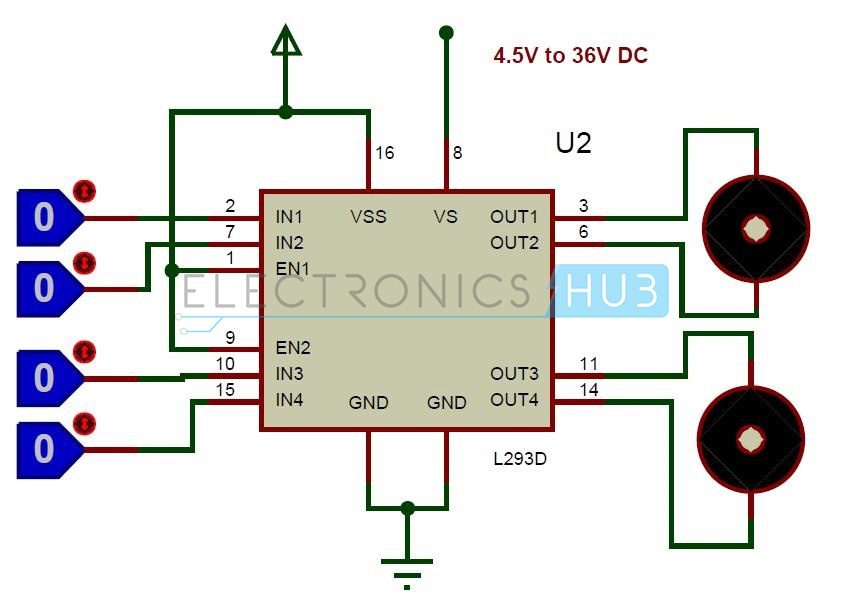
We will be referring the motor driver IC as L293D only. L293D has 16 pins. The L293D is a 16 pin IC, with eight pins, on each side, dedicated to the controlling of a motor. There are 2 INPUT pins, 2 OUTPUT pins and 1 ENABLE pin for each motor. L293D consist of two H-bridge.

H-bridge is the simplest circuit for controlling a low current rated motor. - Pin Characteristics • 1 - Enable 1-2, when this is HIGH the left part of the IC will work and when it is low the left part won’t work.• 2 - INPUT 1, when this pin is HIGH the current will flow though output 1• 3 - OUTPUT 1, this pin should be connected to one of the terminal of motor• 4,5 - GND, ground pins• 6 - OUTPUT 2, this pin should be connected to one of the terminal of motor• 7 - INPUT 2, when this pin is HIGH the current will flow though output 2• 8 - VCC2, this is the voltage which will be supplied to the motor. • 16 - VCC1, this is the power source to the IC. So, this pin should be supplied with 5 V• 15 - INPUT 4, when this pin is HIGH the current will flow though output 4• 14 - OUTPUT 4, this pin should be connected to one of the terminal of motor• 13,12 - GND, ground pins• 11 - OUTPUT 3, this pin should be connected to one of the terminal of motor• 10 - INPUT 3, when this pin is HIGH the current will flow though output 3• 9 - Enable 3-4, when this is HIGH the right part of the IC will work and when it is low the right part won’t work.